Good Morning! I'm new to using CAD models. I only used them in class. I created a manual plane, line, point alignment to make the model aligned with the machine. The problem I'm having is when I change my alignment or workplane, my points are no longer aligned with my model. They are offset and mess up my dimensions. Do I need to continually redo the manual alignment to keep everything where it should be or am I missing something else? Thanks in advance!
If you do not physically move the sphere, re-home the machine or physically alter the probe build (replace, remove or re-tighten any part of it) then you should only answer YES and take a manual hit to locate the sphere for your first tip. This is what is commonly refered to as the "master" tip is usually A0/B0. All subsequent tips can then be calibrated by answering NO to the "has the sphere moved" question. There are many, many, many posts on the forum that explain this in detail so a quick search should yield the information you need.
WhiteRabbit We'll get to the bottom of this. To set up auto cal commands successfully, one must do the following:
0.5) Have a SET position for your sphere to be screwed into
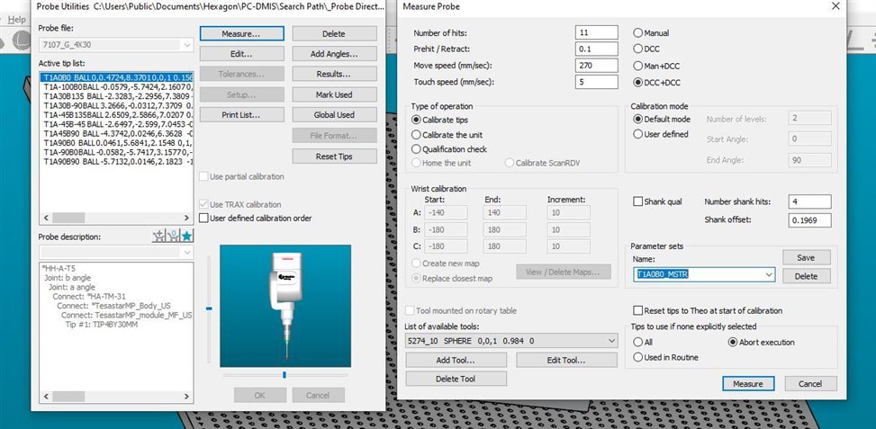
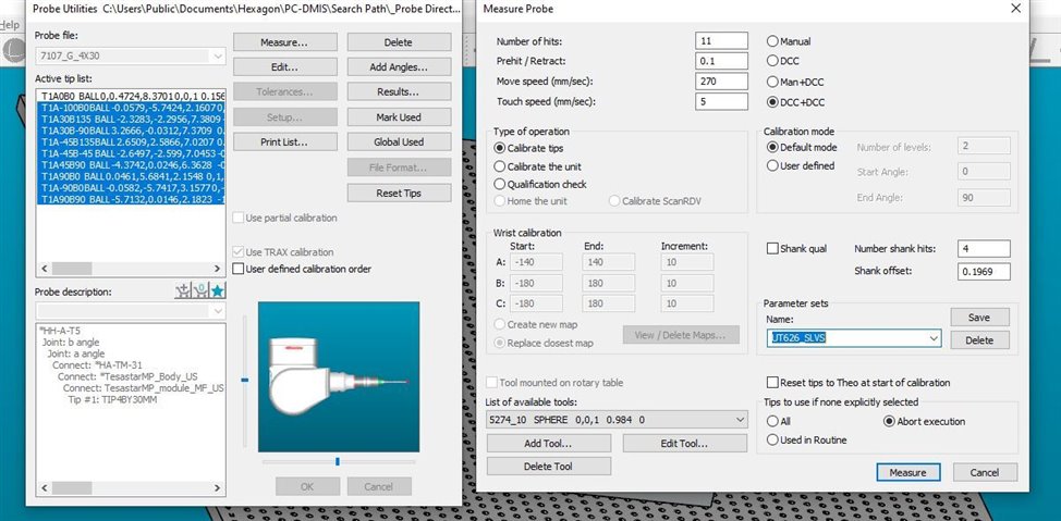
1) Create the PARAMETER SET for your MASTER PROBE. This "PS" should be T1A0B0 only.
2) Create the PS for your SLAVE probe angles. I do this by clicking MARK ALL, then hold "CTRL" and click T1A0B0 to "un-select" it. Now, make these tip angles a PS.
For both parameter sets, DCC + DCC should be checked off.
3) Put the auto-calibration commands in your program. They'll be "blank" when you first insert them. You want to get them into your edit window, we'll then F9 them to add stuff to them.
**
Steps 4 and 5 are the most important part,, probably where you got tripped up
4) F9 the first auto-cal command. Select Your MASTER PS from the drop-down menu.
MAKE SURE YOU SELECT "YES" FOR THE QUAL TOOL MOVED." 5) F9 the second auto-cal command. Select Your SLAVE PS from the drop-down menu.
MAKE SURE YOU SELECT "NO" FOR THE QUAL TOOL MOVED."
Selecting
YES above tells PC DMIS that this "set" is your MASTER. Selecting
NO to the subsequent sets will make PC DMIS view those as the slave files that are relative to the master.
The code is now done, but you're not home free just yet. To make all of the above work, you WILL have to longhand calibrate T1AB0 ONE TIME (calibrating by F9-ing into probe menu and clicking T1A0B0 and saying YES sphere has moved) to tell PC DMIS where it is. Once that finishes, PC DMIS now knows where the sphere is. NOW, you'll be able to run your auto-calibration commands and the machine will do everything automatically for you.
Below is how I handle auto-cal commands. I put them in a group at the beginning of every program and handle it with a YES/NO question and some case & IF statements:
GROUP_PROBEQUAL_FLOWCOMMANDS=GROUP/SHOWALLPARAMS=YES
QUAL_QUESTION =COMMENT/YESNO,NO,FULL SCREEN=NO,AUTO-CONTINUE=NO,
Has the CMM been calibrated??
IF_GOTO/QUAL_QUESTION.INPUT=="YES",GOTO = LABEL_END_CALGROUP
QUAL_ACTION =COMMENT/INPUT,NO,FULL SCREEN=NO,
1--> Let's calibrate the CMM now.

2--> Just run the program. I
don't need to calibrate.

3--> I need help.

IF_GOTO/LEN(QUAL_ACTION.INPUT)<>1,GOTO = QUAL_ACTION
ASSIGN/VAR_1=ARRAY(1,2,3)
ASSIGN/VAR_2=MIN(ABS(VAR_1-QUAL_ACTION.INPUT))
IF_GOTO/VAR_2<>0,GOTO = QUAL_ACTION
SELECT/QUAL_ACTION.INPUT
CASE/1
CHECK/0.25,1
DISPLAYPRECISION/7
COMMENT/OPER,NO,FULL SCREEN=NO,AUTO-CONTINUE=NO,
Ensure sphere is in calibration hole.

Remove cap from sphere.

Press OK to continue.
AUTOCALIBRATE/PROBE, PARAMETER_SET=T1A0B0_MSTR, QUALTOOL_MOVED=YES_DCC,
CHECK COLLISION=NO, SHOW_SUMMARY=NO, OVERWRITE_RESULTSFILE=NO
AUTOCALIBRATE/PROBE, PARAMETER_SET=UT626_SLVS, QUALTOOL_MOVED=NO,
CHECK COLLISION=NO, SHOW_SUMMARY=NO, OVERWRITE_RESULTSFILE=NO
COMMENT/OPER,NO,FULL SCREEN=NO,AUTO-CONTINUE=NO,
Put cap back on sphere.

Press OK to continue.
DISPLAYPRECISION/4
GOTO/TERMINUS
END_CASE/
CASE/2
COMMENT/REPT,

CMM Operator states that CMM is not calibrated and has decided to use it anyway,.
GOTO/LABEL_END_CALGROUP
END_CASE/
CASE/3
GOTO/TERMINUS
END_CASE/
END_SELECT/
CHECK/0.1,1
LABEL_END_CALGROUP =LABEL/
ENDPRG =LABEL/
ENDGROUP/ID=GROUP_PROBEQUAL_FLOWCOMMANDS
This was my problem the whole time! Calibration issue! ramatic Sigh: Thank you everyone for all your help, suggestions, and patience; I'm sure I'll have more questions for you guys soon!
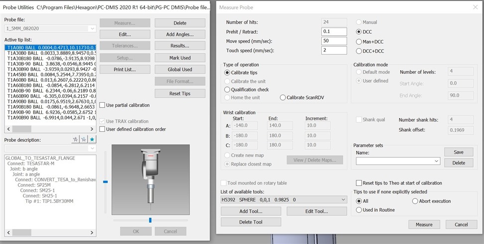
Quick question. I noticed in
DAN_M pic of the calibration details (great stuff) that almost everything in the 'Measure Probe' window is NOT greyed out. With mine, everything is greyed out unless I select a Partial Calibration. I'm just curious, is this something that I'm missing? I believe I have calibration issues. At times I feel like I have it down, then at other times I feel confused because my A90B180 tip will take a point in a different Z location than if I took that same hit in A90B0 or A0B0, etc. Sorry if this isn't truly related, I can make a new post.
Your options are greyed out because you are using a Renishaw SP25. The SP25 has to use a Renishaw supplied algorithm for calibration so anything that would conflict with this is greyed out to prevent people from adversely affecting the calibration. When you choose partial calibration, it follows a greatly reduced procedure which only updates the probe offsets and touch trigger parameters so you have greater control over what you can change.
pguillory if you mean that the A90/B180 takes hits off centre to the sphere then that is usually due to an error in the probe build. Essentially PC-Dmis thinks the probe is a different length to what it actually is because you have either added an additional component to the build or left one out. A common mistake is confusing 20mm and 21mm styli or forgetting to include an adaptor or extension in the component list. If you're absolutely sure the physical probe build matches the component list then it could be that the probe file contains bad offsets - normally caused by not correctly following the "master probe" approach that has been discussed at length in many posts on this forum. If this is the case you would need to either reset your tips or in extreme cases, delete and re-create your probe file.
neil.challinor Okay, that makes sense. I was actually referring to Z hits off my part in relation to the CAD. More specifically, if I create an auto vector point at location 1 and take the hit, when I take that same hit in a different probe angle the Z of the same hit will be off in Z.