hexagon logo

True position of tapered hole

Hello everyone
I need to inspect TP of a tapered through hole on a cylindrical surface at a distance of R. 10.4 from center of part as shown in image,
any thoughts on how this can be inspected..

Attached Files
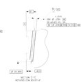
  • is each end of the hole a different diameter? I don't think its a tapered hole, just a .250 hole drilled at a 6 deg angle. I can't see all your datums but the TP shouldn't be an issue.

    The .410 on the bottom would be an intersection point from the axis of the cylinder and center of the arc?


    Sorry my mistake, its an angled hole and all the diameters are same.
    can we do it by neglecting arc?
    as we wont be able to accurately measure center of arc
  • Are your probes fixed or can you set their angle and rotation?
  • As always, apologies if I have stated the overly obvious, or am in fact completely wrong
    1. orient 1 hole to an axis (Ex: X)
    2. offset alignment to 6 degrees (Ex: rotate Z+ around Y)
    3. take a cylinder or a set of circles in bore (Ex: X location should be offset from the 0.410 location by 0.1051 for every INCH of height)
    4. construct a circle on the Z+ plane the bore pierces, that is the one to use for your TP
    5. make a pattern of the CYL/CIR - angle is 12.8571 degrees and repeat 27 times
    6. paste with pattern
    7. set alignment to -B-A-C- and DIM TP of the circles
    Edit:
    looking at this I don't think it would translate the 6 degrees angle for each hole.
  • IMNSHO.... Each hole needs to have its own alignment based on the basic dimensions specified on the drawing, yes, 28 alignments including the 6° rotation and paste with pattern may not be your best option but it will work. I would use paste with pattern for the first measured feature to create the other 27 diameter measurements (including move points). Once everything has been measured, create the individual offset alignments for each hole tolerancing the position when the alignments are created. For each dimension each XYZ nominal should be zero
  • my probes can rotate but the holes are at very less height from near surface, so i'm trying to inspect it using pins