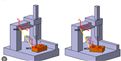
I'm trying to run a program, but I am having trouble with the manual alignment. After I do the manual alignment, the X and Z planes seem to align fine, but I'm having an issue with the Y plane. The triangles for the features line up fine on the X and Z planes on my model, but not the Y plane. That triangle is lined up at an angle, almost perpendicular to the plane. The part is set up with the A datum facing up, the B datum facing the front, and the C datum facing the left. I'm not sure what I'm doing wrong. I did not make this program, I'm only running it. Any help would be appreciated as I'm fairly new to this.
Here's the alignment code:
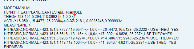
MODE/MANUAL
PLN43 =FEAT/PLANE,CARTESIAN,TRIANGLE
THEO/<423.151,5.294,118.8992>,<1,0,0>
ACTL/<16.0501,15.4477,-25.2336>,<-0.0012161,-0.0035246,0.999993>
MEAS/PLANE,4
HIT/BASIC,NORMAL,<423.151,9.7727,119.9541>,<1,0,0>,<20 .4472,16.5123,-25.2222>,USE THEO=YES
HIT/BASIC,NORMAL,<423.151,6.5616,118.115>,<1,0,0>,<17. 302,14.6626,-25.237>,USE THEO=YES
HIT/BASIC,NORMAL,<423.151,3.6986,119.4274>,<1,0,0>,<14 .4867,15.9948,-25.2367>,USE THEO=YES
HIT/BASIC,NORMAL,<423.151,1.143,118.1004>,<1,0,0>,<11. 9643,14.6211,-25.2384>,USE THEO=YES
ENDMEAS/
PLN44 =FEAT/PLANE,CARTESIAN,TRIANGLE
THEO/<423.011,4.8205,117.9503>,<0,0.0033451,-0.9999944>
ACTL/<15.6279,14.4506,-25.3096>,<0.0006071,-0.0418502,-0.9991237>
MEAS/PLANE,4
HIT/BASIC,NORMAL,<423.0401,0.6384,117.9363>,<0,0.00334 51,-0.9999944>,<11.4265,14.3896,-25.3096>,USE THEO=YES
HIT/BASIC,NORMAL,<422.9986,3.536,117.946>,<0,0.0033451 ,-0.9999944>,<14.1521,14.4292,-25.3096>,USE THEO=YES
HIT/BASIC,NORMAL,<423.0015,6.2199,117.955>,<0,0.003345 1,-0.9999944>,<17.0844,14.4721,-25.3096>,USE THEO=YES
HIT/BASIC,NORMAL,<423.0039,8.8876,117.9639>,<0,0.00334 51,-0.9999944>,<19.8486,14.5114,-25.3095>,USE THEO=YES
ENDMEAS/
PLN45 =FEAT/PLANE,CARTESIAN,TRIANGLE
THEO/<423.3828,0.135,118.7816>,<0,-1,0>
ACTL/<10.916,15.2595,-24.9973>,<-0.9999332,-0.0115001,0.0011613>
MEAS/PLANE,4
HIT/BASIC,NORMAL,<423.021,0.135,118.1357>,<0,-1,0>,<10.9233,14.5876,-25.3228>,USE THEO=YES
HIT/BASIC,NORMAL,<423.0137,0.135,119.3576>,<0,-1,0>,<10.9079,15.9373,-25.3228>,USE THEO=YES
HIT/BASIC,NORMAL,<423.7614,0.135,119.3822>,<0,-1,0>,<10.9089,15.9012,-24.6718>,USE THEO=YES
HIT/BASIC,NORMAL,<423.7351,0.135,118.2508>,<0,-1,0>,<10.9239,14.6118,-24.6718>,USE THEO=YES
ENDMEAS/
A1 =ALIGNMENT/START,RECALL:STARTUP,LIST=YES
ALIGNMENT/LEVEL,ZPLUS,PLN43
ALIGNMENT/TRANS,ZAXIS,PLN43
ALIGNMENT/ROTATE,YMINUS,TO,PLN44,ABOUT,ZPLUS
ALIGNMENT/TRANS,YAXIS,PLN44
ALIGNMENT/TRANS,XAXIS,PLN45
ALIGNMENT/TRANS,YAXIS,PLN44
ALIGNMENT/TRANS,ZAXIS,PLN43
ALIGNMENT/END
MODE/DCC
CLEARP/ZPLUS,1,ZPLUS,0,ON
PLN46 =FEAT/PLANE,CARTESIAN,TRIANGLE
THEO/<5.1776,0.9517,0>,<0,0,1>
ACTL/<4.6301,1.9256,-0.0003>,<0.0010232,0.0014577,0.9999984>
MEAS/PLANE,4
MOVE/CLEARPLANE
HIT/BASIC,NORMAL,<9.5806,1.9509,0>,<0,0,1>,<9.0154,3.0 005,-0.0065>,USE THEO=YES
HIT/BASIC,NORMAL,<6.4933,0.1485,0>,<0,0,1>,<5.9596,1.1 452,-0.0004>,USE THEO=YES
HIT/BASIC,NORMAL,<3.637,1.4947,0>,<0,0,1>,<3.0805,2.44 2,0.0006>,USE THEO=YES
HIT/BASIC,NORMAL,<0.9994,0.2127,0>,<0,0,1>,<0.4654,1.1 148,0.0054>,USE THEO=YES
ENDMEAS/
PLN47 =FEAT/PLANE,CARTESIAN,TRIANGLE
THEO/<5.0938,0,-0.1359>,<0,-1,0>
ACTL/<4.5627,0.9731,-0.1355>,<0.0172533,-0.9995023,0.0264114>
MEAS/PLANE,4
MOVE/CLEARPLANE
HIT/BASIC,NORMAL,<0.543,0,-0.1369>,<0,-1,0>,<0.0133,0.894,-0.1306>,USE THEO=YES
HIT/BASIC,NORMAL,<3.7315,0,-0.134>,<0,-1,0>,<3.2013,0.9489,-0.1312>,USE THEO=YES
HIT/BASIC,NORMAL,<6.9319,0,-0.1307>,<0,-1,0>,<6.4012,1.004,-0.1313>,USE THEO=YES
HIT/BASIC,NORMAL,<9.1686,0,-0.1419>,<0,-1,0>,<8.6375,1.0426,-0.1449>,USE THEO=YES
ENDMEAS/
PLN48 =FEAT/PLANE,CARTESIAN,TRIANGLE
THEO/<0,0.8373,0.2192>,<-0.9999944,0.0033451,0>
ACTL/<-0.5438,1.7223,0.2247>,<-0.9998986,-0.0138768,0.0032097>
MEAS/PLANE,4
MOVE/CLEARPLANE
HIT/BASIC,NORMAL,<-0.0022,0.2028,-0.129>,<-0.9999944,0.0033451,0>,<-0.536,1.0867,-0.1225>,USE THEO=YES
HIT/BASIC,NORMAL,<0.002,1.4324,-0.1328>,<-0.9999944,0.0033451,0>,<-0.5531,2.3162,-0.1282>,USE THEO=YES
HIT/BASIC,NORMAL,<0.0019,1.4066,0.5244>,<-0.9999944,0.0033451,0>,<-0.552,2.2914,0.5291>,USE THEO=YES
HIT/BASIC,NORMAL,<-0.0018,0.3072,0.6143>,<-0.9999944,0.0033451,0>,<-0.5367,1.1923,0.6207>,USE THEO=YES
ENDMEAS/
A2 =ALIGNMENT/START,RECALL:STARTUP,LIST=YES
ALIGNMENT/LEVEL,ZPLUS,PLN46
ALIGNMENT/TRANS,ZAXIS,PLN46
ALIGNMENT/ROTATE,YMINUS,TO,PLN47,ABOUT,ZPLUS
ALIGNMENT/TRANS,YAXIS,PLN47
ALIGNMENT/TRANS,XAXIS,PLN48
ALIGNMENT/END