hexagon logo

Help with a profile callout

Hello all!

Fast question for the following callout:


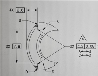
The callout is for controlling these 2 "L" shaped pockets(?!). This is actually half the part as there is a mirror half on the right side (thus the 2x and 4x designations on the basic dimensions). I am a bit confused as the 2.6 basic dimension is restricting translation of the vertical planes while the callout has no datums in the callout. Is this correct?

How would you control this in a no CAD program? Thanks in advance for your advices Slight smile
  • I'd say the TED's are for locating the pockets during measurement (and their THEO's). When it comes to evaluating the profile, no datums should be used and only the form of the pockets are checked.
  • Don't forget that because there are no datums, both profile callouts must be evaluated simultaneously. You will need to use either XactMeasure or the Geometric Tolerance command to do this, depending on what version of PC-DMIS you have - legacy cannot perform simultaneous evaluations. Also, because you don't have a CAD model, you will need to make sure the nominals are correct and will not be able to use iterate and re-pierce.
  • thanks for the answer. It is kinda confusing tbh and at the end of the day I would be interested to know if this indeed correct. For the vertical axis is using the 7.8 basic dimensions between the profiles that are controlled. I am wondering if it would be more correct to do the same with the horizontal axis as there is a mirror side.

    On the pcdmis programming side, would a constructed feature set / scan of 2 autoplanes would be enough to dimension with the profile callout you think? What would the best non CAD approach to controlling this?
  • As long as your THEO's are correct, it should suffice with four autoplanes.
  • neil.challinor

    Don't forget that because there are no datums, both profile callouts must be evaluated simultaneously. You will need to use either XactMeasure or the Geometric Tolerance command to do this, depending on what version of PC-DMIS you have - legacy cannot perform simultaneous evaluations. Also, because you don't have a CAD model, you will need to make sure the nominals are correct and will not be able to use iterate and re-pierce.


    I am not sure to understand this. Since there is no datum I would imagine they care only about the form error. By controlling them simultaneously, I am making the 7.8 basic dimension being part of the evaluation (and subsequently more important than the 2.6 one), aren't I? I use version 2017 R2 btw.
  • I think you need to ask whoever supplied the drawing to you. Are there any other callouts controlling those pockets back to any datums? To me, it seems they want to control the relationship of the pockets to each other (because of the 7.8 basic dimension) and they want to control the relationship of the pockets to the top of the outer radius (using the 2.6 basic dimension). You would need an additional callout to control the 2.6 but evaluating the two profiles simultaneously will maintain the 7.8 relationship. Evaluated separately, each profile will be free to optimize as much as it needs to in order to minimise the form and size deviation and they will not relate to each other at all.
  • neil.challinor
    This cannot be done with legacy using a scan set of the points/scans on both areas combined, then using Vector-Min/Max form only profile? This would essentially check them simultaneously
  • neil.challinor So I am right to assume that by controlling them simultaneously the 7.8 gets involved in the profile (while 2.6 is neglected) as far as pcdimis calculation is concerned right? There is no other callout to control these pockets. For me strictly following the callout, we need to not measure them simultaneously. The basics as they are, are a mistake imo and either datums should be used or change the 2.6 to follow the 7.8 tactic (dimension the horizontal distance between the mirror vertical planes) and evaluate all 4 pockets at the same time. Thoughts? ​
  • you need to ask the designer / your customer. I'm basing my assumption for the simultaneous requirement on the ASME rules. Since you say there are no other callouts for these pockets on the drawing then, in my opinion, the drawing is incomplete and to guess at the design intent would run the risk of failing to inspect the part properly.