hexagon logo

PROBE TIP NOT VISIBLE FOR NEWLY INSTALLED/ALIGNED 50mm POINT PROBE 85443-03

BOUGHT A NEW 50mm PROBE-POINT-MULTI GAGE 85443-03. USED ON ABSOLUTE 85 ARM RUNNING PC_DMIS 2020R1/ RDS 5.4
WENT THROUGH THE ALIGNMENT PROCEDURE OF A NEW PROBE IN RDS. RESIDUAL ERROR AND CALCULATION RESULTS ARE WITH IN SPEC LIMITS.

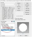
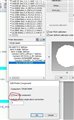
ABLE TO INSERT PROBE INTO A PROGRAM BUT THE GRAPHICS SCREEN SHOWS ONLY THE BASE OF THE PROBE AND NOT THE TIP. SEEING THE PROBE TIP ON THE SCREEN COMPARED TO THE PART IS THE WHOLE IDEA OF THE GRAPHICS SCREEN.

DID HEXAGON PROPERLY PROGRAM THIS PROBE CORRECTLY??? IT IS A PURCHASED PROBE FROM HEXAGON AND SHOULD WORK COMPLETELY

SEE ATTACHED 3mm PROBE WITH TIP VS POINT PROBE WITH OUT TIP

ANY IDEAS ?
  • operation>calibrate>active probe>make sure the probe tip is drawn(double click on the probe tip and check the DRAW TIP box)
  • The edit probe data window opened, but their is no draw tip box to check...only various data field boxes with info or zeros.
    Probe utilities shows a "reset tip" button, but i don't want to mess with it at this time.
    ???
  • The edit probe data window opened, but their is no draw tip box to check...only various data field boxes with info or zeros.
    Probe utilities shows a "reset tip" button, but i don't want to mess with it at this time.
    ???
  • n527999

    try this

    double click on the tip

    Attached Files
  • IT'S NOT SHOWING A TIP TO CLIP...ONLY THE DESCRIPTION NAME I GAVE IT.
    THE EDIT PROBE COMPONENT BOX OPENED BUT IT SHOWS THE DRAW THIS COMPONENT BOX IS CHECKED.
    HEXAGON ASSURED ME THAT I WOULD ONLY NEED TO ALIGN IT...NOT BUILD IT.

    I HAVE A 2ND POINT PROBE (PACKAGE DEAL) AND A 2mm BALL STYLUS THAT I WAN'T TO SWAP ONTO IT. NOT EVEN GOING TO BEGIN TRYING TO FIGURE THAT OUT.

    ANYWAY, THANKS FOR THE ASSIST.
  • 1: CAPSLOCK is not the best means of communication.

    2: Hexagon sells probes as a consumable component. Hexagon has no means of affirming what machine and components are necessary for your specific probe build, which has, is, and will always be, the-end user's responsibility.

    --Open your existing probe that works. Use windows' "snipping tool" to screen-capture the bottom left box of the probe build.
    -Now, click into your newly-created probe file.
    -Duplicate all the screen-snipped probe build info, until you get to where the stylus screws into the machine.
    -Now to build your probe, unfortunately, I can't find a product named anything simlar to "50mm PROBE-POINT-MULTI GAGE 85443-03", so i'm flying blind with guidance on how to "Build" this probe.
    As an example however, you can certainly reference a 40mm ss or cf extension and then a 3mm dia x 10mm long stylus tip to get a 3x50 probe built.