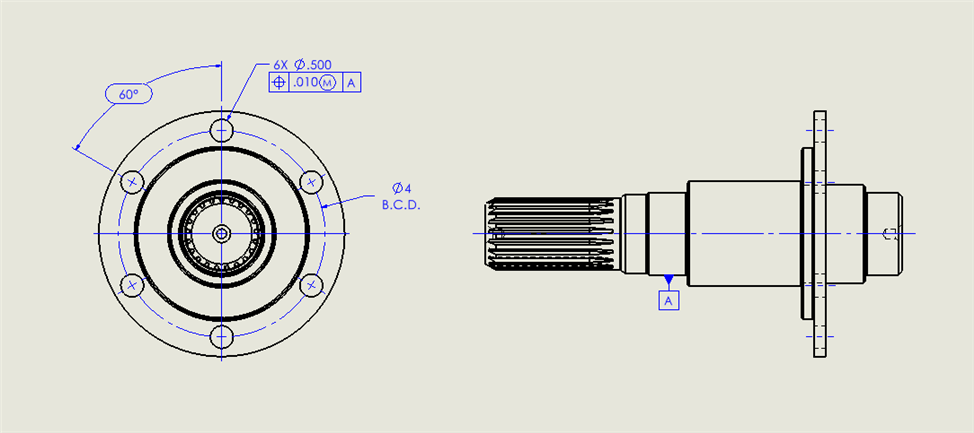
I don't know what this true position on the hole is constraining. Bolt circle diameter or orientation of the hole maybe? Trying to determine if I need to measure the hole as a cylinder. Appreciate the help.
The tolerance zones for the six holes are six cylinders of (initially) Ø0.01 (over the full length of the flange).
These 6 cylinders are fixed in relation to each other (so they are all parallel to one another) and spaced as shown by the basic values on the drawing (60° and on a 4" diameter).
These cylinders, are controlled to Datum A, so they are all also parallel to datum A and, and the centre of the 4" pattern is located on the axis of datum A. This pattern of tolerance zones can rotate freely about datum A to best encompass the measured holes.
The given Ø0.1 tolerance is followed by (m) which means that tolerance (Ø0.01) applies when they're at their Maximum Material Condition - for a hole, it has the maximum amount of material when it's at its smallest size. As each hole deviates away from its smallest size, you gain additional tolerance (and as the tolerance zone is a diametrical value you can simply add the difference in diameter straight on to the 0.01)
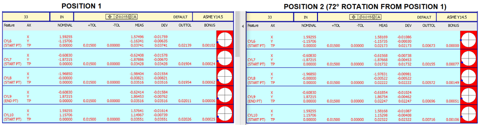
As mentioned above (by way of formula) the TP value is double the radial deviation from the nominal centre to the measured centre (because the tolerance zone is diametrical the measured deviation must also be reported in a diametrical way).
Except that the machinist who programs the toolpath will always start with drilling one hole preferably the one along center axes & move the tool at those angle intervals along the radius (dia/2) from that hole. So that one automatically hole becomes rotation tertiary datum.
The machinist can do whatever they want as long as the part meets print requirements when they are done with it. Our job is to measure the part, using the full amount of tolerance available.
I have a similar part and can tell I'm doing something wrong. This part has 5 holes in the flange and I got all 5. I noticed the x,y deviation is always in the same direction on my parts. So I rotated one part and measured again and the direction stayed the same. The datum A used is a cylinder measured in dcc with 2 levels. Getting different values so I know something aint right but perplexed as to why the true position is always off in the same direction.
Good guess. Yep the datum is measured with an extended stylus at an angle and the holes measured with a shorty probe vertical. How do you calibrate probes with respect to each other?
Use only one probe/tip combo to define the reference sphere location.
Probably use the shorter probe build for this. Tip A0B0, this will be your 'master' probe.
First I'd reset the tips (there's a button on the probe utilities window for this).
Then calibrate it answering 'yes the sphere has moved' when prompted.
if you are calibrating any other angles on this probe at the same time they will be calibrated correctly in relation to your master probe (the first tip calibrated will define the reference sphere location)
Reset the tips on the second probe. Calibrate this answering 'no the sphere has not moved'.
Tip A0B0 of the master probe is the only tip you ever use the define the reference sphere with.
So if you move the sphere, or take it off and out it back in the same location you must always calibrate the m6atter probe (yes sphere has moved). All other probes or tip angles (no sphere has not moved).
And our job is to inspect part like it was manufactured. Too many times a designer designs the component one way, it's made a another way & it's checked yet another way. No wonder all the bickering going one back & forth.
MattR: Gonna have to disagree with you. As Quality Control, our primary job is to ensure that the part meets requirements. Manufacturing's job is to ensure that the part is made to requirements. Design's job is to ensure that a functional, manufacturable part is conceived and communicated. This doesn't mean that we won't work with manufacturing and design to ensure a good product. At the end of the day though, all of our jobs is to ensure that the best possible product is produced and delivered to the customer in a timely manner. Final inspection of a part like it was manufactured is asking for trouble. Parts can often easily meet manufacturing's plan but don't fully meet design's requirements. Thats not to say that QC won't help execute manufacturing's plan but ultimately our responsibility is to ensure print requirements are met.