I have been asked to measure lead on a cylindrical machined surface. Is PC-DMIS capable of this measurement, and if so how would you go about programming the measurement?
@ Jim
a drawing is indeed helpful for your question. Or at least a few dimensions of how big the cylinder is.
Unless it's super thin or super long, it shouldn't be a problem.
what equipment is available to you is also helpful.
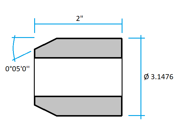
Thanks for the response. The outside cylinder is 3.1476 inches in diameter. There is a 2" length of the outer cylinder that calls for no lead. The lead angle us to be 0 degrees + or - .05. They call for a string test for this feature but that seems barbaric when I have a CMM with analog scanning capabilities next to me.
Yes we do have an optical comparator and that has been suggested. The company that we are manufacturing the part for, states they check the lead with a CMM. We may end up checking it with a comparator but I would like to find out if the CMM can do it and determine the correct process if it can.
You could measure the area with no lead as a circle, then measure the extreme end of where the lead is allowed to be as a circle. do an assignment to subtract the difference in diameters, divide by 2 and report that if I'm understanding you correctly.
did I sketch everything correctly?
however, either the starting point as a diameter or the length of this "lead" is still missing.
if you have all the normal values then you can measure an auto-cone there quite normally.
If you don't have all the normal values available, measuring is pointless anyway
If you have an analogue scanning probe, you can do a linear scan in the axial direction along the first 2 inches of the cylinder. Measure the cylinder with as high a point density and as many levels as is practical to achieve accurate results (for both the size and orientation of the cylinder) and then construct an adjust filter from your scan, using the Cylinder measurement as the reference input:
PC-DMIS Help Center - 2023.1 (hexagonmi.com). This will correct any 3D error induced by the probe drifting in and out of section as you scan. You can now dimension profile of your adjust filter and turn on graphical analysis so that you can visually see if there is any lead or not - this essentially replicates the optical comparator check. You can also level to your cylinder, rotate from the cylinder centroid to the adjust filter, select the appropriate workplane and construct a 2D line from your adjust filter. You can then dimension the angle between your 2D line and the cylinder axis.
The HUGE caveat with all this though is that you need to take into account the total measurement uncertainty of your system. +0/-0.05° over a 2" length is quite a tight tolerance to hit and, depending on what CMM and probing system you are using, you may find it is not accurate enough.
I have been experimenting with scanning the surface very similar to your suggestion. I have scanned a part without lead and also a part that has a definite lead. When you graph each you can clearly see the difference between the two. The part with lead graph has a definite pattern (frequency) where the part with no lead is very irregular and does not have a pattern (frequency). From the graph I can see the distance of the lead in one revolution and can calculate the lead angle. Obviously I am unable to calculate the angle from the no lead part since there is no pattern and lead distance cannot be determined.
It would be nice to have PC-DMIS report the angle but I have not been able to determine how to do that yet. Still working on it though.