hexagon logo

Alignment using only two datums

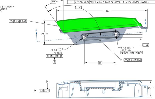
I've attached an image of a part I'm working on and I always get confused by seeing only two datums I'm not sure how to go about creating my alignment my alignment I know this is basic stuff but I'm with limited training on top of being the only operator In the company so there is no mentor/co-worker to turn to please keep answers simplistic as I previously stated I am basically self-taught and terminology isn't my strong suite as of yet. Please and Thanks to all in advance. I can add more info as needed just let me know. 

Parents
  • Looking at this I would suggest creating a plane on the A datum (looks like it's the counter bore of the hole) and levelling to that and setting it as your Z origin.
    Then measure the 2 Ø8.8 to create a midpoint as others have mentioned and set that as x, y origin.
    I would rotate between the two Ø8.8 bores and then rotate out the error so that the part is aligned with drawing.
    To do this take the x and y between the two bores x=65 y=5.69 use trig to find the angle: Tan-1(5.69/65) = 5.00283153° and rotate the alignment by this figure.

  • That worked flawlessly... now that have my MAN/DCC align is it good practice to then remeasure those datums with more hits to find any deviations during my dimensioning process....

    One more thing as of right now anyway ,Grin I've for the most part taught myself how to read the FCF W, or W/O modifiers (MMC, LMC) unfortunately this is where I'm stuck, I know datum B is in some cases to be considered at mmc aka the most material smallest hole but how or what is best practice to measure, and dimension the call out let's say 

    ø6.5 ± 0.13
    (2)plus.
    |Position| 0.25(m)|A|B(m)|

    I had to use the word "Position" in place of the symbol.

    Again, thanks for everyone input!!!

  • I've personally used GeoTol for most things, although I've used legacy at times as well.   has given people examples in the past as to why GeoTol might be the better choice, depending on what you're after.  I personally would use GeoTol in your current scenario because of the MMB modifier in your FCFs and having to use the simultaneous tolerance evaluation in reporting your characteristics (FCFs that reference the same datums in the same order at the same material boundaries should be simultaneously evaluated).

  •   You should definitely use the Geometric Tolerance command for this part as opposed to Legacy dimensioning.  In addition to what has already been said regarding MMB, there is also the simultaneous requirement to consider.  According to ASME Y14.5, all position and profile feature control frames which reference the same datums, in the same order and at the same material condition, must be evaluated simultaneously. In your earlier screenshot, I see three feature control frames where this would apply.

    See: Simultaneous requirement - PC-DMIS for CMMs - PC-DMIS - Nexus Community (hexagon.com).

  •  and  thank the both of you for the explanations this really cleared up some of my confusion ill of course post whether everything is working out with program going forward. As well as any more questions that may come up along the way.

  • I think I caught what you were throwing...SO what's the difference between the last EXAMPLE I asked about, And the call out FCF for datum B?

    I know this probably day one material but idk if you noticed where I mentioned I'm basically learning as I go with the help of others such as yourself. my apologies for all this Q/A there is so much information to take into account along with rules and best practices etc. so I really appreciate your patience with this

  • Guess Who??? lol so I finished measuring the port and I'm now working on the starboard side of this part my question once I measure everything, 1. Do I need to make an alignment the part per the Gd&T call outs. And 2. will you break down how I'd go about doing this so I get the correct numbers. I've attempted this with other parts and I've not had much luck when it comes to  MMC and all that because I don't quite understand how to go about using the software to give me the right numbers. A good example of this is that I don't know when it would be better to use a constructed feature vs and auto or measured feature in order to get the right dimension??? I really appreciate any help I can get thank you in advance and if I need to, I can screenshot some of my code if that would help clear up any confusion in the multiple questions I just asked.

  • If you are using GeoTol for your GD&T callouts, you should not need to align to the datum structure from the FCF. If you use GeoTol you'll see the "alignment" XYZ origin it is using with a Yellow line and blue arrow point if your cursor is at that dimension command in the edit window.

    Although, from what I can see of your print, you probably are already mostly aligned to the part if you followed the datum structure.

    If you are using Legacy Dimensioning for them, yes you will have to be correctly aligned. I'd suggest like others have said to use GeoTol if you aren't already

  • I'm not sure if anyone mentioned this to you but when using GeoTol you have to define your datums.  With Legacy your alignment is made up of your datum structure but with GeoTol you need to go to insert-->dimension-->define datums.  From there, select what features you want to act as your datums.  After that, you can start calling out your characteristics.  Just remember that in order to use the MMB for datum references, their sizes need to be called out before the considered features that are referencing those datums.

  • You can also begin typing "datdef" in the Edit Window, and F9 that command, or just type in the ID after the =

    Or when you are in the GeoTol Window, if you click the + button without any datums defined, you can define them right there

    DATDEF/A,FEATURES=CIR1,,
    DATDEF/B,FEATURES=CIR3,,

  • can you elaborate on the MMB using gel tol command a little more. I'm sorry I'm struggling the terminology what does it mean when you said to make sure that the sizes be called out before I reference the datums?? my apologies if this is frustrating, I am beyond greatful for everyone who's taken the time to walk through this with me.

  • Before calling out the position of the 6.5 dia. features, first call out the size(s) of datum B.  As the datum B diameters grow, more datum shift will be allowed and the software needs to know how much datum shift there is by considering the actual sizes of the datum B pattern features.  In  's screen shot above, you'll see that beside datum B, there's <MC>.  Click on that to apply datum B's MMB.

Reply Children
No Data