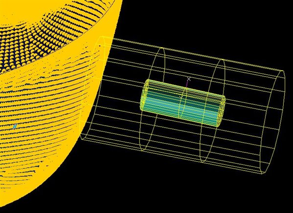
Hello, I am trying to simulate a birdstrike using Patran as my preprocessor. At the time of creating an ALE coupling between the surface and the bird. What are the parameters which have to be used (surface, 3d elements, etc) in order to fullfill the coupling? Can somebody please explain step by step what should be done?
Hi, we generally do not use the ALE method anymore in Dytran as we have more features, speedup and ease of use with the General/Fast Coupling method. Please see the example Multiple Birdstrike on Box Structure in the Dytran Example Problem Manual Chapter 4.
The main process with this approach is that the structure and fluid domains are completely separate and you define a coupling surface of the structure you want to interact with. We then use the Mesh Generator in LBC to define the fluid mesh virtually that will be created by Dytran when the solve starts. Therefore you don't need a physical fluid mesh anymore and it is much easier to resize and move around. Coupled to this is the Initial Euler Conditions in the LBC that use shapes to define which fluid material is where and what their initial states are (density, velocity, energy). Lastly using the new PEULER1 property set you do not need to assign it to any physical elements as it is used to connect these items above together and define which Euler solver is required (multi material, full stress tensor etc).
Hi, according to your advice I have used the General Coupling but it does not look similar in any way to the example. I have been using the problem as a reference but I still have some doubts and many errors. This are some of the things that have been done:
1) The bird has been meshed using 3D elements with the sweep and extrude method available in Patran. Is that correct?
2) Initial euler conditions have been defined (shape, initial values (speed), region definition)
3) ALE Grid 1 coupling has been set too. (All elements were selected)
4) When defining General Coupling, the flow is defined as out, and porosity coeff as zero. As to the application region, do I have to just select the elements that compose the surface which is being impacted by the bird?
1) Usually we only use the geometric regions to define the environment and specific material regions using the Init.Cond.Euler ->Shape option with either Sphere or Cylinders. But in the case of more complicated shapes then you can mesh a closed surface (and assign these the special Dummy Shell 2D properties) and then use the Shape/Surface option.
2) So using the Init.Cond.Euler you then define the Shape/Surface for the bird region, a large sphere for the void region and then Initial values for the bird material and lastly Region Definition sets up the 1st level for void and second level for bird
3/4) You do not use the ALE Coupling inputs, but rather only the General Coupling input option where you pick the closed structural surface that your fluid will interact. Porosity is zero (this is used for subsurfaces to define open sections). Then the Cover option means which side of the closed surface will be ignored regarding fluid. Therefore if set to Cover=Inside, it means you will only look at fluid region outside the structure which is what you'd want for birdstrike.
I will see if I can rework the introduction training workshop into a SimCompanion article and link it below.
Regarding the 1.IND error this is a material orientation angle on the CQUAD etc cards in the BDF file that were not translated correctly from Patran. Please verify the element orientations again and use the orientation flag in the PCOMP property set or where you have any inputs. Alternatively remove them if not required as it could be an artifact from a previous file import or something. You can also set the translation option to free format that might help sort it in Analysis | Translation Parameters : Card Format=Free
Regarding the FSI setup. Thanks for the pic, it makes things a bit easier to talk around.
I'm still working on the FSI setup article, so will link it soon(!). But the steps you need to do that I would recommend is:
1. Finalise the structural model. Meaning get the structural model well defined and even run a test model with it just in space to make sure that part of the analysis is initialising correctly (materials/properties/LBC etc).
2. Set up the coupling. Create | Coupling | General. For your structure set the Cover=Inside and select all the external elements (making sure you only select a closed surface). Most times it is easier to make a new group with only the external surface mesh and use the Element tools like Verify | Element Boundaries to make sure that the surface is indeed closed.
3. Now start the FSI side of things. Firstly by creating all the fluid material. In your case then only the bird material. For birdstrike always remember to add shear strength too! Otherwise with only bulk modulus it is like a water balloon! Create | Isotropic | NonLinElas (DMAT) will give you bulk modulus (Coeff A1) and shear modulus (Shear Coeff G0). Because we do birdstrike in void it is important to set the spallation pressure to -1bar. By default in Dytran we spall/cavitate fluid material when the pressure =0, so if you work in void we need to offset this so that we work in a pseudo 'gauge' pressure and spall at -atmospheric pressure.
4. Because we are going to use the abstract fluid domains/regions/mesh we first need to define which fluid solver we'll use. For this create the 3D Euler Property and since our fluid will have to solve the full stress tensor as we have shear, select the MM/Strength.
The PEULER1 option means we will use geometric regions to define which material goes where and not select from a physical mesh/elements.
5. Fluid Mesh or Euler Initial State can be swapped depending on the setup really. In this case it will be easier to do the Initial state setup first. For birdstrike you generally have a hemispherical ended cylinder and you could generate this with the geometry shapes (sphere/cylinder), but it becomes a pain when you want to move things! Easiest is to mesh a surface mesh that you then assign Dummy Shell properties to:
Then in LBC | Create | Init.Cond.Euler | Shape/Surface to set the shape of the bird select these dummy elements. They will therefore only be used to define the region of material and not take part in the structural analysis (dummy element nodes are fixed in space).
For the rest we will define a shape for the void. For this you can generally just create a very very large sphere :)
This means you can then move the bird around in subsequent runs and not need to worry about redefining the void region.
After this we define the initial values that will go with our shapes. In your case then you only need to define the bird values as void is empty by definition:
Lastly you tie it all together with the region definition defining the order that these shape/initial values are applied to the fluid domain space. Order as in level numbers. So Level 1 is void shape, then Level 2 is bird shape/bird values:
Also see that you select the Euler property set to link these things together.
6. Fluid Mesh. In LBC | Create | Mesh Generator you can now set the fluid mesh up. The Option=Box is for external (or internal) fluid domains, while the Option=Adapt is used to fill a fluid mesh inside a coupling surface (and move with it). You can then Preview and see where your fluid mesh will be, so you can move it around to encapsulate the bird shape and structure you think it will mainly interact with.
A key thing to note is that the boundaries of the MESH boxes are by default walls, so if you want to allow flow to go out you need to add the following in the input deck manually as Patran does not support these MESH flow cards yet:
FLOWDEF,999,,MMSTREN,,,,,,+
+,FLOW,OUT
In the Output requests you need to request outputs for the Euler results for the specific Euler property set used, i.e. ALLMULTIEULSTREN.
For the general coupling we also have a feature called Fast coupling. This is setup in the Analysis | Execution Controls | Coupling Parameters. Set this to Active and also failure if required:
Fast coupling is a slight misnomer. We are able to run 50-70% faster by assuming the fluid mesh is aligned with the global orientation (which it is when using MESH boxes). This means we can ignore the step to transform the flow between Euler elements into global X,Y,Z vectors and use them as is. So best to always switch it on :)
Lastly I would strongly recommend to look at the Dytran User Guide Chapter 11 to see how to use Paraview as post processor as this is a great tool to use for fluid results post-processing (isovolumes etc).
Thank you so much for your help, I am making good progress now. After defining all as you have said I am getting an error related to the coupling surface of my structure. My question is:
Can I select several elements from my mesh in order to define the application region, or do I have to select just a Surface?
This is what happens when I do so:
%E-P3116501-V3_REVERSE_POLYH_V3, , ,
A side of a face in surface SURFACE1 has no other faces attached.
This indicates a hole in the surface.
The mesh and the geometry has been used in several Nastran analysis without any error.
You need to make sure the mesh for the bird is a 'smooth' external surface only mesh, so no T-juntions or internal edges. If you look at these nodes in Patran then you should see what I mean as there is probable an internal mesh. The Verify-Element Boundary might not show it up if the internal mesh is also full closed or connected.
Sorry I just edited the question before, I solved the previous issue. But once I have solved this, this is the error I get regarding the coupling surface. I have selected several shell elements in order to define the application region but I am not sure if I have done it properly because this is what I get:
%E-P3116501-V3_REVERSE_POLYH_V3, , ,
A side of a face in surface SURFACE1 has no other faces attached.
This is a similar issue as the previous initialisation problem. The coupling surface needs to be a closed external surface only of the structure you want to interact with. So it needs to only be a skin of a closed volume so that it can subtract from the fluid domain. The best practice I've used is to put all the structure external surface that will make up the coupling surface into a new group to take a more detailed look at the boundary (no holes) and internal connections (T-Junctions etc). One of our requirements is for a closed surface, so if your structure has holes, then you need to close it with the same Dummy 2D elements as used for the bird shape mesh.