No problem. The quickest way to derive it is by using the law of cosines, but you can also derive it using the Cartesian formula and by letting x = r*cosθ and y = r*sinθ for each point (different r and different θ), substituting, and eventually using the cosine of a difference identity.
Just something I was fiddling around with to try to help machinist who may not have known the formula. In case I'm not around to help them, to raise a red flag on themselves like the sample above .007 maybe they have .010 tolerance "Hey Somethings wrong" because most of the time they have that thinking of +/- .005 for tolerance. I tell them it don't work that way.
MetsoMetrology
KIRBSTER269 I've run into the same issue trying to explain true position to machinists who just want a simple answer like a plus/minus. I ended up printing out a true position chart to give them a general idea and now I can show them another way. Thanks!
KIRBSTER269 Very interesting approximation. How did you come up with that? Pattern spotting? Trial and error?
Obviously the approximation and the true calculation yield the same result if one of the deviations is equal to 0. Oddly enough, they yield the same result if one deviation is 8/15 of the other. For example, assume Δx = .0015 and Δy = .0008. Your approximation yields position error of 2(.0015) + .0008/2 = .0034 and the exact calculation yields .0034. In this case, Δy = 8Δx/15. You can analyze further to find a local minimum in the error function at Δy = Δx/sqrt(15), the case in which the error in the approximation is approximately 6.4% of Δx. The local maximum in the error function will be when Δy = Δx, the case in which the error in the approximation is approximately 32.8% of Δx.
I’m interested in how you discovered this approximation because I’m wondering if there is another easy approximation that has different behavior as Δx and Δy get farther apart.
I just thought very simple
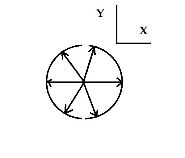
JacobCheverie sometimes its as simple as drawing. I have a starting point in Zero and I'm going to recreate the deviated circle from scratch. treat each side as a radius. I took my highest reading moved my center point in the X direction .0032 with a protractor, I created one radius in the Xplus direction, then another in the XMinus direction, circle was complete, but I didn't account for the Y, but I couldn't draw anymore because my circle was complete, no more radius to draw??? so knowing everything is controlled from the CENTER all I could control with the Y is a point my center point, I Can't disrupt my radius on each side. Knowing it's .0012 off in the Y direction but that's .0006 from each side, I'll split the difference. Now That I've established a new center point .0032 in the X direction, knowing that I'm only going to draw 2 Radii in worst case direction X now move the point half the deviation in Y, because I'm not drawing any radii in the Y direction, so let's get that protractor back out and recreate those 2 radii in the X direction. Well it looks good on paper, does the math work out?? Take my highest reading to control each Radius (times 2) take low reading split the difference (divided by 2) add them together what do I got? Pretty Da_mn close. Then I try different numbers just to see. I haven't found an example that didn't work yet. Sometimes if you over think, Well your just over thinking it.
Sorry for bringing this subject back up, but I also wanted everyone to understand that my theory also applies to telling the machinist technically the same thing, when making adjustments. For instance right now, I have a part the holes he drilled are .0058 off in X and .0028 in Y. I will tell him to go .0058 in the correct direction of X and .0014 in the direction of Y. This is important not to use the full deviation in both directions.
Sorry for bringing this subject back up, but I also wanted everyone to understand that my theory also applies to telling the machinist technically the same thing, when making adjustments. For instance right now, I have a part the holes he drilled are .0058 off in X and .0028 in Y. I will tell him to go .0058 in the correct direction of X and .0014 in the direction of Y. This is important not to use the full deviation in both directions.
Can you explain why it is important not to use the full deviation in both directions? Why wouldn't the machinist correct the full amount of X and Y to bring the holes back to nominal?