
Hello,
I am new to CMM programing and have hit a snag. I am trying to create a plane sperate from my CAD drawling so I can raise my part off the granite. How ever I need this plan to allow me to zero it. Like you would do for a manual CMM. When I went to program the plane, I told the vectors that it was <0,0,1> instead of <0,0, -1> . I leveled and origin to the plane in both manual and DCC. Then moved working with the CAD drawling, I was hoping that when I create a plane on the inside of the part that it would recognize that the part was on top of the plane.
How ever after I finished doing the manual and DCC alignments for the actual CAD drawling and then went to do the first play though, the CMM errored out each time after trying to take the first four hits for the plane underneath the CAD drawling.
So, my question is, is it possible to create a raised plane off the granite and if so,, how do you do this? Any help would be greatly appreciated, thank you for your time.

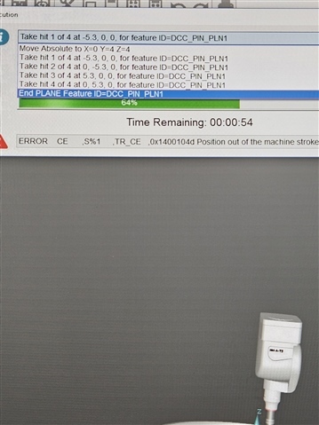
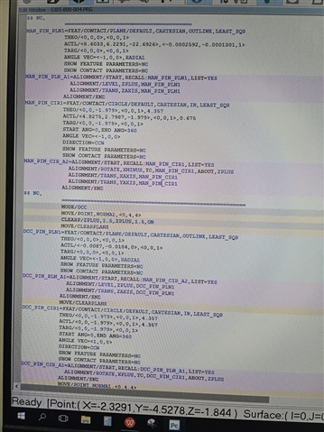
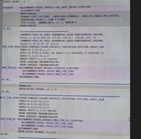 Here is my code. I Have told my vector to be <0,0,1> and both of my planes are the same. But when I run it states my points are our of location. Though it is odd that they are calling out the points as bad when the -5.3 is the distance I put as the spacer for my plane points.
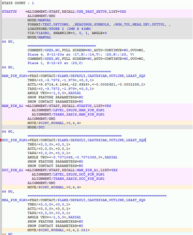 I wrote more code and now it will run, but it is trying to find the upper left-hand corner, after I take my four manual points.
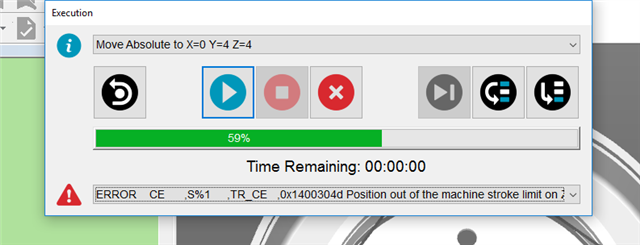
 I was able to figure out why the CMM was going to the upper left conner I had forgotten to align my coordinates to match the physical part. Then I created a circle to align my X&Y. But I am still getting the error out of stroke zone. The CMM thinks that my PIN_PLN is at -18.8402 instead of just zero. I do not know why it keeps doing this. Am I missing a step? Thank you for your time.
 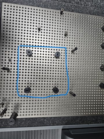 The pins inside the blue square are the ones I am trying to zero out on. The two to the right are what I am pushing it up against the one on the left center is the front centering point (mostly for reference). I can't show a picture of the part sorry. I have a diameter in the middle of my part that needs to be taken but when I try to run it without the stand offs, the prob errors out on the granite.