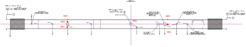
I want to see with everyone's expertise on how I should set up this alignment off the Datums. There is Datum Target A1 and A2. and Datum B. How should I Tackle this? Attached is a layout of the Datums. Thank you for any help.
A1/A2 = Cylinder evaluations
B = Circle
A1-A2 = Line for axis (Level/Origin = 4 DOF)
B = Rotate about axis, origin along axis (=2DOF)
You now have all 6 DOF handled.
Beware, that the GDT reporting will not see all 6DOF controlled, it will only work for you in your alignment and legacy reporting.
Thank you Very Much for your help R2. One other question. so I should level both Cylinders and then create a line and then Rotate Datum B and then Translate the 2 remaining Axis to Datum B?
When i manually measure Datum B and then measure the 2 outside cylinders, I created a plane (Mid Point) and did YPlus and leveled , I then rotate Datum B and then Translate the 2 remaining axis to Datum B, My Datum B is off in space. So i'm doing something incorrectly.
Assuming your A1/A2 line runs along the Y axis:
Level axis line Yplus/minus (2 DOF)
Rotate B about line (1 DOF) <-most likely rotate to Zplus as required about Y
Origin line - X/Z (2 DOF)
Origin B - Y (1 DOF)
That will handle the 6 DOF.
In my opinion, you should start with collecting the cylinders making a temp axis from those manual inputs, then measure B and complete the temporary alignment. Now repeat the process with DCC and beef up the hits used. This should enable you to have a good foundation to move forward with.
Would this be the first alignment in your program? If so, tubes can be very difficult on the initial alignment. I generally do an iterative alignment first for the machine to find the part, then continue with what R2 is telling you above for the 2nd Alignment. It just works easier for me than figuring out what PCDMIS is trying to do.
Points 1 and 2 will be on a curve, but I still hit the points coming straight down on them. Then 2 hits from the side pnts 4 and 5, then an end stop point if you will. I used pnt6 in the b datum, but you could use the end of the part if you think the length is close enough. Also for points 4 and 5 you could use holes with points in that direction. Its always worked for me. I don't do tubes very often anymore. but I'm sure it will at least help your machine find the part.
One circle at A1
One circle at A2
3D-line between them
Primary alignment on this line (X?)
Circle in datum B
Secondary alignment between 3D-line and datum B circle (Y?)
X origin in datum B circle
YZ origin in 3D-line
Assuming your A1/A2 line runs along the Y axis: Level axis line Yplus/minus (2 DOF) Rotate B about line (1 DOF) <-most likely rotate to Zplus as required about Y Origin line - X/Z (2 DOF) Origin B - Y (1 DOF)
That will handle the 6 DOF.
In my opinion, you should start with collecting the cylinders making a temp axis from those manual inputs, then measure B and complete the temporary alignment. Now repeat the process with DCC and beef up the hits used. This should enable you to have a good foundation to move forward with.